Oilybits Coolant / Cutting Fluid, Tramp Oil Separating & De-Odourising System
Working Principle:
- A built-in Air Operated Diaphragm Pump sucks contaminated coolant from the CNC machines sump.
- Coolant flows through a stainless steel re-useable strainer.
- Coolant flows through a moulded honeycomb device made of a special non-lipophilic substance, where Tramp Oil is separated from Coolant by surface tension
- Separated Tramp Oil is collected in an external vessel (such as a jerrycan) and clean Coolant flows back to the CNC machines sump.
- An optional Ozone Generator (Models with Z Suffix) injects ozone into the coolant sump to control bacteria for disinfection and deodorisation.
Key Features of Tramp Oil Separating System:
- No ongoing consumables cost
- Improved product finish.
- Reduced production / machine downtime.
- Extended Coolant change period.
- Reduced waste, and associated environmental impact.
- Reduced cost of Coolant.
- Reduced cost of storage and disposal of waste Coolant.
- CE Approved.
- Available in 110v50Hz1Ph, 230v50hz1ph and 400v50hz3ph.
Key Features of optional Ozone Generator, De-Odourising System:
- No ongoing consumables cost (uses air & oxygen directly from the room)
- Disinfection and De-odourisation of Coolant.
- CE Approved.
- Available in 110v50Hz1Ph, and 230v50hz1ph.
Options| Model | Voltage | Dimensions (mm) | Weight (Kg) | Flow Rate (LPH) | Ozone Capacity (g/hr) |
| CPSm 360 | 230v50Hz1Ph | 250 x 500 x 850 | 40 | 360 | None |
| CPS 360 | 400v50Hz3Ph | 250 x 500 x 850 | 40 | 360 | None |
| CPSm 360Z | 230v50Hz1Ph | 500 x 500 x 850 | 70 | 360 | 2 |
| CPS 360Z | 400v50Hz3Ph | 500 x 500 x 850 | 70 | 360 | 2 |
| CPSm 1200 | 230v50Hz1Ph | 410 x 600 x 950 | 100 | 1200 | None |
| CPS 1200 | 400v50Hz3Ph | 410 x 600 x 950 | 100 | 1200 | None |
| CPSm 1200Z | 230v50Hz1Ph | 810 x 600 x 950 | 140 | 1200 | 5 |
| CPS 1200Z | 400v50Hz3Ph | 810 x 600 x 950 | 140 | 1200 | 5 |
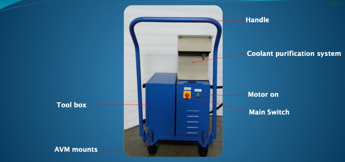
Below: Front
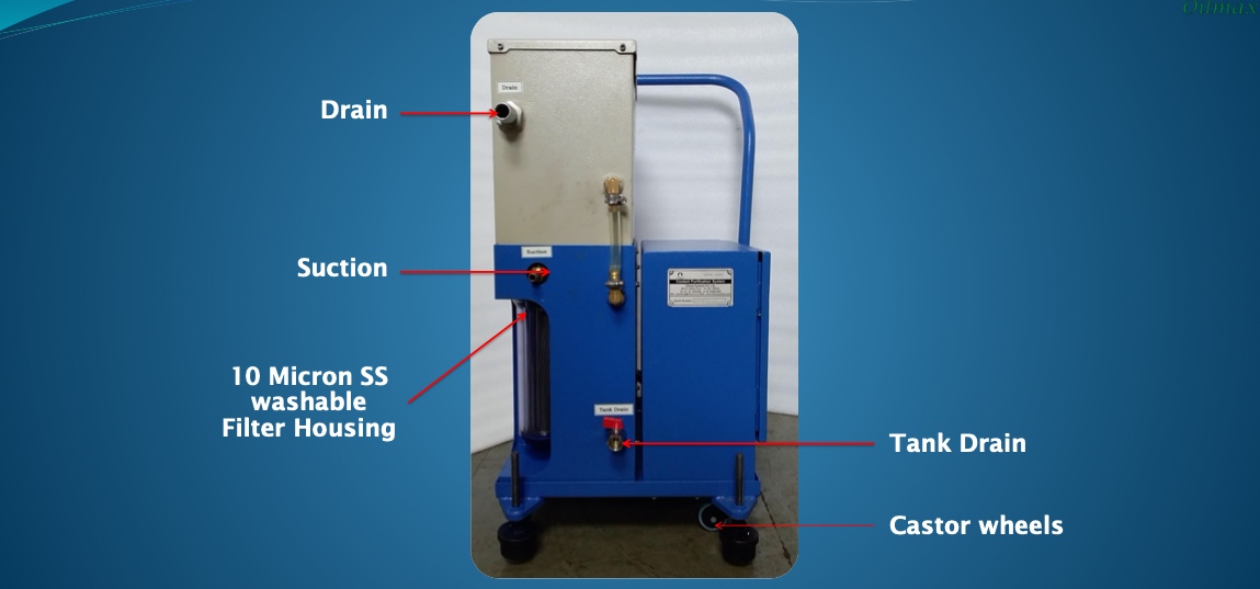
Below: Rear
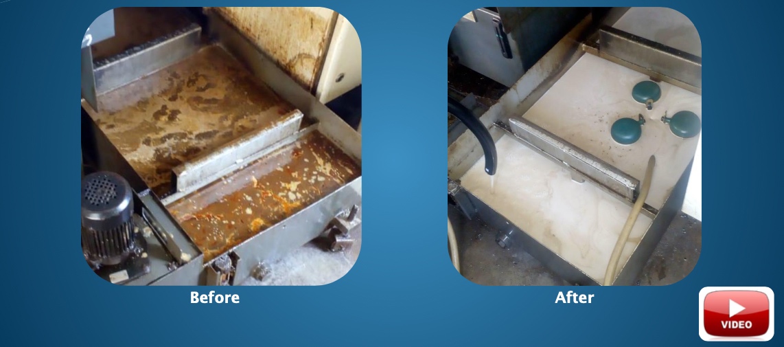
Below: Before & After
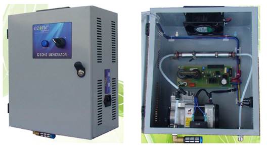
Below: Inside Ozone Generator, showing inlet air filter before air pump, which just needs brushing off occasionally, and Corona Discharge Tube, where ozone is created.
 Download Ozone Generator Brochure PDF
Customers who bought this also bought…